Setting a clock should be a thing of the past. There are enough radio signals bouncing around that provide a reasonable time-sync. Mobile phones do this based on the cell towers they’re in contact with. There are radio-based clocks that use the NIST Radio Station WWVB. Networked computers set their time via NTP or similar protocols. Still, it’s pretty rare to self-setting travel clock.
Most of those “atomic” clocks will only work in the Continental United States. They rely on the radios signals coming from Fort Collins, Colorado. If you travel outside of North America, it seems you’ll be stuck manually setting clocks. I think we can do better. This project attempts to build a better clock.
There are multiple ways to get a clock to set itself. Radio clocks, as mentioned above, a limited in their geographic coverage. The time signal from cell towers would limit you to populated errors. There are also possible compatibility issues with different frequency bands used in different parts of the world. This leaves using a satellite based solution like GPS, GNSS, and/or GLONASS.
This is the route I took.
The Hardware Side
I’d already made use of Raspberry Pi for time services on my local network. Expanding on this work for a travel clock meant finding a reasonable screen and assuming that there wouldn’t be a network available. I wanted to make the device as stand-alone as possible, so having some inputs through the GPIO also seemed ideal.
Thankfully, the Pi community is vast and there are a large number of options available. My parts list looked like the following.
Parts List
- Raspberry Pi Zero W
- WaveShare 1.3” OLED display HAT
- NMEA 0183 compatible GPS chip
- Vibrating Motor
- A Pi Zero Case
- Soldering iron, solder, electrical tape
Any Pi with a 40 pin header will work, but the WaveShare 1.3” HAT has the same dimensions of Pi Zero. This makes packaging more straight forward and compact.
Assembly
Using the WaveShare OLED HAT both simplifies and complicates the wiring. The diagram below represents just the wiring for the GPS module and vibrating motor since the HAT just pushes onto the GPIO header.

The OLED HAT ends up occupying all the pins of the GPIO header. That would normally make it difficult to add anything else to the GPIO pins. My solution was to solder the male header to the Pi “upside down.” The longer pins going from the top of the Pi Zero through to the underside. This exposed the GPIO pins on the bottom of the Pi even after mounting the OLED HAT. It does mean you need to do some mental gymnastics to get your pins right when soldering your GPS and vibrating motor.
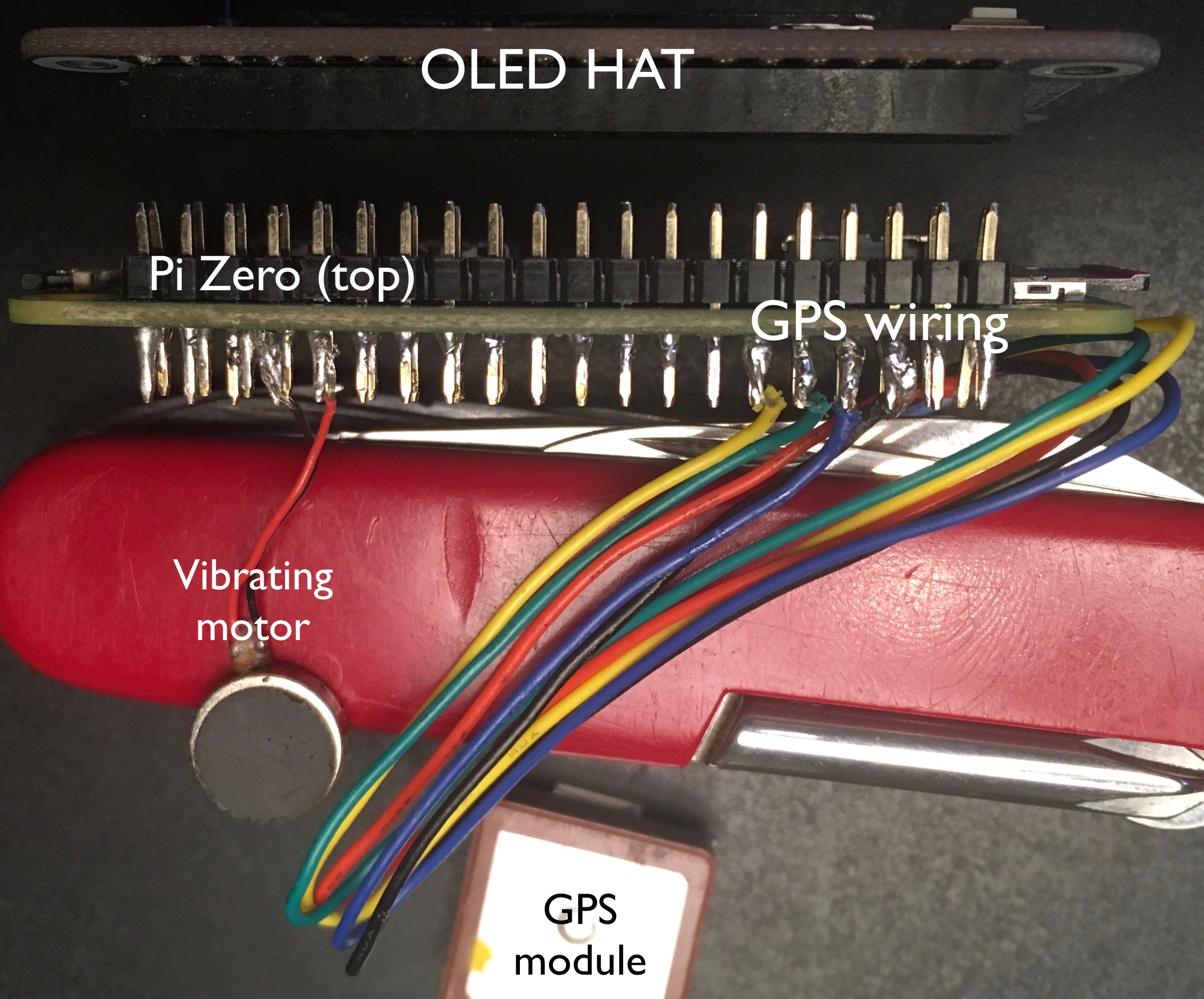
The above shows my sloppy soldering in action and how the parts align with each other.
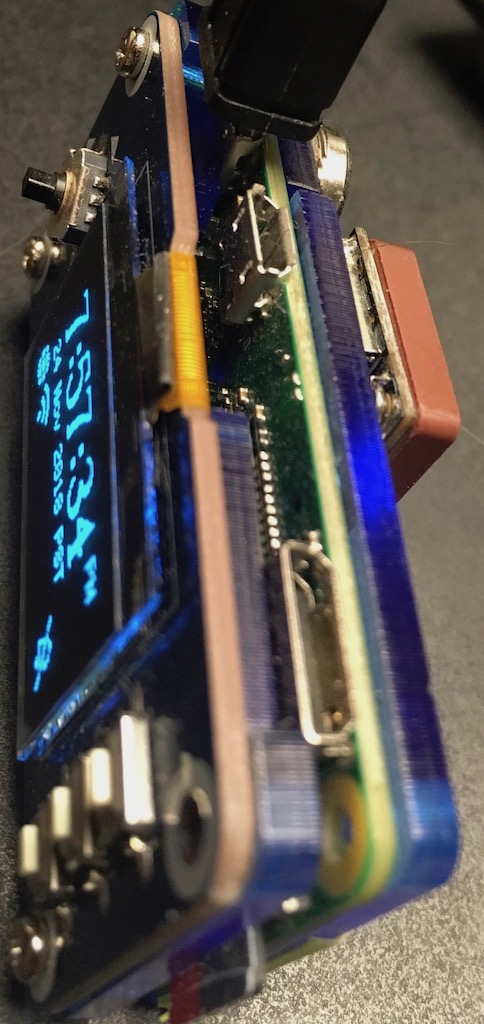
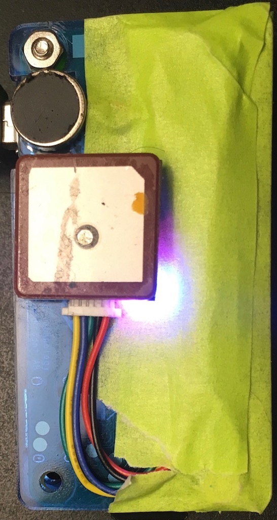
A top side and rear image of the clock fully assembled (yes, I lost a screw). I used double-sided tape to hold the GPS module onto the Pi Zero case. Painters tape is covering up the Pi header and holding down the wires.
Pi Setup
I started with a fresh install of Raspbian Stretch Lite.
After initial boot-up and disk partiotion expansion, I ran
raspi-config to adjust keyboard, Timzeone (UTC), turn on ssh, and
rename host. Before rebooting, I then ran apt update; apt -y upgrade
to make sure the OS and other associated bits are up to date.
Lastly, I ran rpi-update for latest firmware, then reboot again.
From this point, I typically detached the Pi from monitor and keyboard
and just remotely access the machine via ssh.
Packages
There are few additional packages we need to support NTP, GPS devices, and cloning the pi Travel Clock repository. The following will install those required packages (yes, I use vim, yet I typed this out in emacs).
apt install ntp ntp-doc ntpstat gpsd gpsd-clients pps-tools git vim libjpeg9-dev libjpeg9
Boot Configuration
A few tweaks to the Pi’s boot configuration are necessary to enable GPIO for the OLED screen, buttons, GPS, and vibrating motor.
/boot/cmdline.txt
The default /boot/cmdline.txt file enables serial console. We’ll
need to disable this. In your favorite editor open up
/boot/cmdline.txt and remove console=serial0,115200 console=tty1.
The /boot/cmdline.txt is a single line file that should read something like the following:
dwc_otg.lpm_enable=0 root=PARTUUID=73d822ba-02 rootfstype=ext4 elevator=deadline fsck.repair=yes rootwait
Do NOT copy the above verbatim as the root=PARTUUID= will be
unique to your SD card.
/boot/config.txt
Updating the /boot/config.txt file as follows will enable the GPIO
pins we need and disable bluetooth. I disable bluetooth to conserve a
bit a power.
## Turn on i2c and spi interfaces
dtparam=i2c_arm=on
dtparam=spi=on
## Setup PPS on GPIO pin 18 and allow 17 to output
dtoverlay=pps-gpio,gpiopin=18,gpio_out_pin=17
## Enable and set serial interface for GPS at 9600 baud
enable_uart=1
init_uart_baud=9600
## disable bluetooth
dtoverlay=pi3-disable-bt

# Enable audio (loads snd_bcm2835)
dtparam=audio=on
gpu_mem=32
Run the following command before your next reboot in order to disable the bluetooth daemon.
systemctl disable bluetooth
Now reboot your Pi and we’ll setup the rest of the software.
GPS Setup
The Pi Travel Clock uses a GPS chip for two purposes:
- As a time source for NTP.
- Location source for time zone determination.
Both functions are provided through the gpsd service interfaces.
gpsd configuration
Edit your /etc/default/gpsd file a follows:
DEVICES="/dev/serial0 /dev/pps0"

# Other options you want to pass to gpsd
GPSD_OPTIONS="-n"
Testing GPS
After performing the above and rebooting the system you can validate GPS is working and readable by running:
$ echo '?WATCH={"json":true,"pps":true,"enable":true};' | nc localhost 2947
{"class":"VERSION","release":"3.16","rev":"3.16-4","proto_major":3,"proto_minor":11}
{"class":"DEVICES","devices":[]}
{"class":"WATCH","enable":true,"json":true,"nmea":false,"raw":0,"scaled":false,"timing":false,"split24":false,"pps":true}
{"class":"TOFF","device":"/dev/serial0","real_sec":1534311753, "real_nsec":687999963,"clock_sec":1534311752,"clock_nsec":391569000}
{"class":"TPV","device":"/dev/serial0","mode":3,"time":"2018-08-15T05:42:33.000Z","ept":0.005,"lat":37.507011635,"lon":-122.280264485,"alt":63.728,"epx":48.519,"epy":55.650,"epv":171.560,"track":0.0000,"speed":0.000,"climb":0.000,"eps":111.30,"epc":343.12}
{"class":"PPS","device":"/dev/pps0","real_sec":1534311754, "real_nsec":0,"clock_sec":1534311753,"clock_nsec":191607000,"precision":-20}
{"class":"PPS","device":"/dev/pps0","real_sec":1534311754, "real_nsec":0,"clock_sec":1534311753,"clock_nsec":191607000,"precision":-20}
{"class":"TOFF","device":"/dev/serial0","real_sec":1534311754, "real_nsec":687999963,"clock_sec":1534311753,"clock_nsec":392180000}
{"class":"TPV","device":"/dev/serial0","mode":3,"time":"2018-08-15T05:42:34.000Z","ept":0.005,"lat":37.507011635,"lon":-122.280264485,"alt":63.728,"epx":48.519,"epy":55.650,"epv":171.560,"track":0.0000,"speed":0.000,"climb":0.000,"eps":111.30,"epc":343.12}
{"class":"PPS","device":"/dev/pps0","real_sec":1534311755, "real_nsec":0,"clock_sec":1534311754,"clock_nsec":191617000,"precision":-20}
{"class":"PPS","device":"/dev/pps0","real_sec":1534311755, "real_nsec":0,"clock_sec":1534311754,"clock_nsec":191617000,"precision":-20}
{"class":"SKY","device":"/dev/serial0","time":"2018-08-15T05:42:35.000Z","xdop":3.23,"ydop":3.71,"vdop":7.46,"tdop":7.06,"hdop":5.00,"gdop":11.39,"pdop":8.94,"satellites":[{"PRN":22,"el":88,"az":211,"ss":34,"used":true},{"PRN":31,"el":40,"az":46,"ss":33,"used":true},{"PRN":3,"el":65,"az":316,"ss":21,"used":true},{"PRN":14,"el":25,"az":66,"ss":20,"used":true},{"PRN":16,"el":17,"az":141,"ss":21,"used":true},{"PRN":11,"el":12,"az":216,"ss":20,"used":true},{"PRN":1,"el":38,"az":222,"ss":17,"used":true}]}
{"class":"TOFF","device":"/dev/serial0","real_sec":1534311755, "real_nsec":687999963,"clock_sec":1534311754,"clock_nsec":617024000}
{"class":"TPV","device":"/dev/serial0","mode":3,"time":"2018-08-15T05:42:35.000Z","ept":0.005,"lat":37.507011635,"lon":-122.280264485,"alt":63.728,"epx":48.519,"epy":55.650,"epv":171.560,"track":0.0000,"speed":0.000,"climb":0.000,"eps":111.30,"epc":343.12}
Ctrl-c to quit.
Depending on your GPS module, an LED should light to indicate that the chip is powered. Additional LEDs or the same power LED will frequently indicate when the chip has GPS lock by blinking once per second or by changing color. If your chip has LEDs and doesn’t light when the Pi is powered, things are probably not wired correctly.
If the chip is powered, but doesn’t get a sync after several minutes, maybe you are in a shielded building. Try moving closer to a window.
cgps and gpsmon will both provide more human reable output to see
the fix, location, time, and satellite information.
Time Setup: NTP
Configuring NTP calls for the editing of /etc/ntp.conf. In your
favorite editor, open up the configuration file make it read like the
following:
driftfile /var/lib/ntp/ntp.drift

# Enable this if you want statistics to be logged.
statsdir /var/log/ntpstats/

## Get from https://www.ietf.org/timezones/data/leap-seconds.list
leapfile /home/piClock/leap-seconds.list

statistics loopstats peerstats clockstats
filegen loopstats file loopstats type day enable
filegen peerstats file peerstats type day enable
filegen clockstats file clockstats type day enable

## gpsd Shared Memory
server 127.127.28.0 minpoll 4 maxpoll 4 prefer
fudge 127.127.28.0 time1 0.000 flag1 1 refid SHM stratum 0

## PPS driver
server 127.127.22.0 minpoll 4 maxpoll 4 prefer
fudge 127.127.22.0 refid PPS
After finishing your edits, restart the ntp service:
systemctl restart ntp
Running ntpq will give you the status of your local NTP service.
$ ntpq -pn
     remote           refid      st t when poll reach   delay   offset  jitter
==============================================================================
*127.127.28.0    .SHM.            1 l   13   16  377    0.000     -3.7   5.081
+127.127.22.0    .PPS.            0 l   11   16  377    0.000    -2.07   0.018
If you are on a network, then the results maybe more like:
$ ntpq -pn
     remote           refid      st t when poll reach   delay   offset  jitter
==============================================================================
x127.127.28.0    .SHM.            1 l   13   16  377    0.000  -3214.7   5.081
x127.127.22.0    .PPS.            0 l   11   16  377    0.000  -220.07   0.018
 0.debian.pool.n .POOL.          16 p    -   64    0    0.000    0.000   0.002
+174.136.103.130 204.123.2.72     2 u  440 1024  327   19.346   -2.489   1.250
+129.250.35.250  249.224.99.213   2 u  440 1024  377   10.930   -1.872   8.665
*38.126.113.11   .CDMA.           1 u 1069 1024  377   13.714   -1.969   2.329
-198.206.133.14  25.151.162.158   3 u  122 1024  377   58.653   -4.290   1.476
-66.135.44.92    162.254.66.243   2 u  592 1024  377   60.341   -4.524   1.708
Get the Clock Going
Now that the hardware, OS, and background support services are configured, we can move forward with downloading the clock code and setting it up.
Download clock code
Clone or otherwise download the Git repository.
$ git clone git@gitlab.com:shackledtodesk/piTravelClock.git
Cloning into 'piTravelClock'...
The authenticity of host 'gitlab.com (35.231.145.151)' can't be established.
ECDSA key fingerprint is SHA256:HbW3g8zUjNSksFbqTiUWPWg2Bq1x8xdGUrliXFzSnUw.
Are you sure you want to continue connecting (yes/no)? yes
Warning: Permanently added 'gitlab.com,35.231.145.151' (ECDSA) to the list of known hosts.
remote: Enumerating objects: 129, done.
remote: Counting objects: 100% (129/129), done.
remote: Compressing objects: 100% (71/71), done.
remote: Total 129 (delta 67), reused 111 (delta 56)
Receiving objects: 100% (129/129), 4.00 MiB | 90.00 KiB/s, done.
Resolving deltas: 100% (67/67), done.
Checking out files: 100% (23/23), done.
Setup python and clock dependencies
$ cd piTravelClock
$ sudo apt -y install python-setuptools python-dev build-essential python-pip
$ pip install -r requirements.txt
Run It Manually
$ sudo ./clock.py
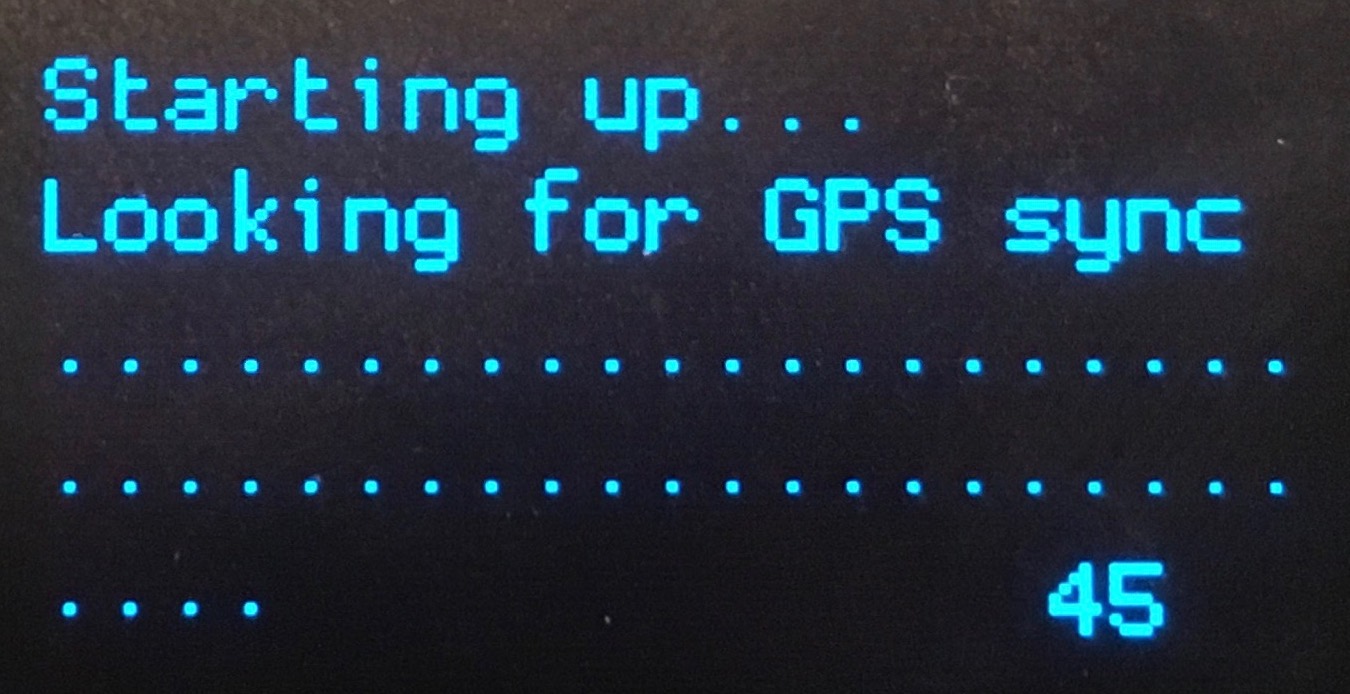
At this point the screen should come on as the device attempts to find GPS lock. It does this in order to attempt to determine the physical location of the device. Typically, though, this will timeout and not find a sync when the clock is first powered on. It can take several minutes before the GPS unit will get enough satellites to get a location lock.
If the clock was powered, but just rebooted, then sync might be found during initialization and the proper timezone will get set. Otherwise, the timezone will default to US/Pacific.
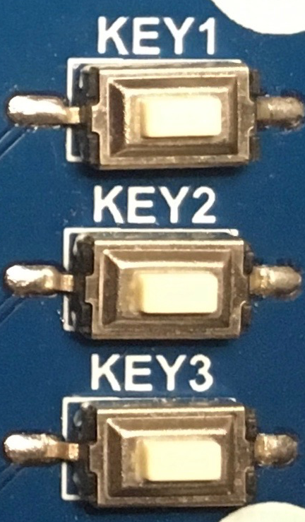
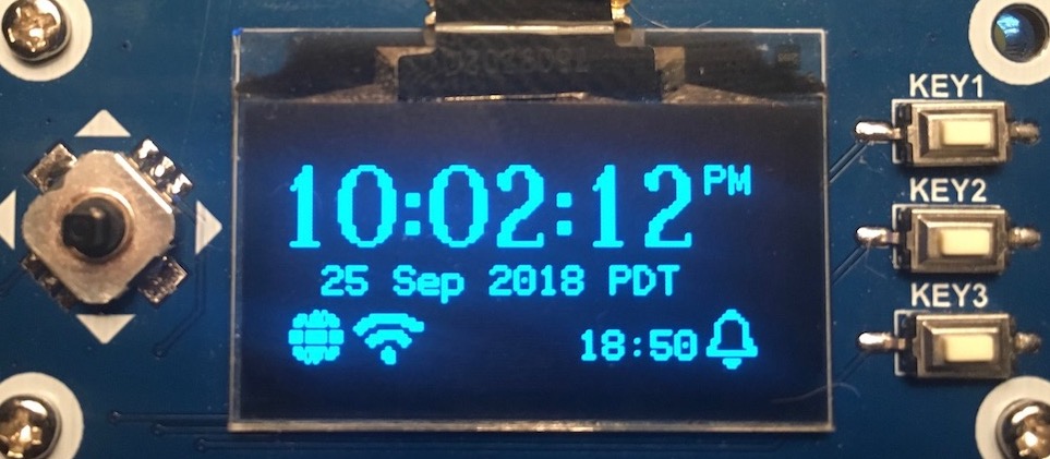
To check to see the status of the GPS, you can hit “Key 1”. This will take you to a GPS information screen that will show the current Latitude, Logitute, Timezone, and whether the GPS is locked. “Key 2” on this screen will re-query the GPS module to see if sync has been achieved. “Key 1” will return you to the normal clock/time screen.
On the clock screen you can switch from the calculated timezone to UTC (GMT) by pressing “Key 2”.
“Key 3” will turn the display off or on.
Finishing It Off
In order to get the clock to start on boot, you’ll need to add some
systemd script.
This can be found in the examples directory. Copy the
start-clock.service to /etc/systemd/system/. You’ll need to edit
this file to have the proper path to clock.py.
Once edited you can run the following enable the service:
systemctl daemon-reload
systemctl enable start-clock
systemctl start start-clock
At this point you should have a functioning clock that will keep accurate time and automatically adjust the timezone based on your location. In a future post, I’ll go through the how to use the clock through the HAT keys and joystick interface.
Todo
This isn’t a finished project by any stretch of the imagination. From a hardware perspective there are 3 things I’d like to be able to do next.
- Add an RTC Clock so that it will maintain a semi-accurate time while powered off.
- Get a nice case and button covers. Possibly something 3d printed as I haven’t found anything that covers my application.
- A battery pack to let it keep running w/o wall power.
There are a bunch more things around the software that need work. We can leave that until the next write up on using the clock.